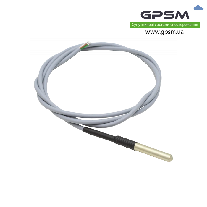
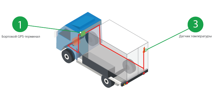
Long-distance transportation of perishable goods is a demanding job that requires increased attention to temperature conditions. A sensor must be installed inside each refrigerator to monitor the efficiency of the refrigeration equipment. This device must also transmit data about the state of the autonomous system to the dispatching console to be able to respond quickly in the event of a breakdown. A digital temperature meter DS18B20 in combination with additional equipment can solve similar problems.
DS18B20 is an electronic device that allows you to take temperature measurements with the subsequent transmission of an alarm to the operator. This device has the following distinctive features:
- Built-in 9 - 12 bit signal converter, which affects the accuracy of incoming readings.
- The boundary conditions for the required temperature range are set by the user and recorded in the built-in memory of the controller.
- The device transmits readings to the dispatcher via the 1-Wire protocol. When used in cold logistics, information is converted via GPS communication.
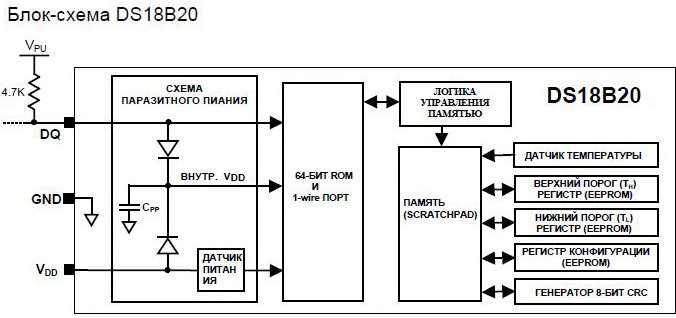
- The meter does not need an external power source, since the voltage supplied through the low-current channel is sufficient for operation to transmit data, accumulated on the capacitor.
- The sensitive sensor allows you to measure the temperature in the room at extreme values - from -55 ℃ to + 125 ℃ - the sheath of the data cable is made of refractory polyvinyl chloride.
- The measurement accuracy is a record 0.5 ℃, in contrast to previous models from this manufacturer. However, this indicator may differ slightly at temperatures below +10 ℃ or above +85 ℃.
Each DS18B20 temperature meter has an individual 64-bit code that identifies a specific product. This provides the ability to connect several controllers at once to a single communication channel, and the devices will not interfere with each other.

Device advantages
The DS18B20 digital temperature meter has some advantages over other competing models:
- Each 1-Wire serves only one data transmission channel from the sensor.
- Several wires can be combined into a single communication line with output to a single indicator located in the control room.
- There is no need to plug into an outlet, as the device becomes active at a voltage of 3 to 5.5 V.
- When the maximum resolution is set to 12 bits, the update rate of the readings on the indicator is 750 ms.
- The user has the ability to set individual alarm parameters.
- When several sensors are connected in parallel in one communication channel, a signal indicating a failure provides information about a specific device that has failed. This allows the dispatcher to quickly identify the problem and issue a command to correct the problem.
- The sensor is fully compatible with the DS1822 software installed on a computer in order to display the measurement results on a monitor.
The considered temperature meter has been widely used and is used in many industries. The device is most often used in the cold logistics of perishable goods.
DS18B20 temperature meter device
The sensor of this model has a built-in 64-bit read-only memory (ROM), which stores a unique identifier. In addition, the microcircuit also contains RAM, which temporarily captures the following data:
- Instant room temperature readings take up 2 bytes of total memory.
- User defined boundary conditions that, when exceeded, will trigger an alarm command. The lower threshold is called Th, the upper one is Tl.
- There is also 1 byte free space in memory for storing user configurations. Using this register, you can set the sensor resolution from 9 to 12 bits in 1-bit steps (9, 10, 11 and 12 bits - 4 modes in total).

Regarding the register of the boundary parameters for triggering the alarm, it is stored in a separate block, independent of electricity, called the EEPROM. This allows the system to receive an alarm in any abnormal situation.
To enable multi-channel connection of the communication line to several devices, a special resistor is used with the following functions:
- The resistor contains a microcontroller that registers the individual code of each of the sensors connected to the communication channel.
- The device allows parallel exchange of incoming data with each connected device.
- The microcontroller is supplied with a bus, and each of the sensors is connected to it, forming a single refrigeration equipment dispatching system.
Independence from the supply line of the device is achieved by the presence of a built-in capacitor on the microcircuit, which accumulates energy from the incoming signal. This element also powers the main chip, providing so-called "parasitic power". If necessary, it is possible to connect the controller through an external power supply by plugging the cable into the Vdd output socket.
How temperature is measured
The main task of the sensor is to transform the real value of the ambient temperature received from the metal probe into a numerical sequence for subsequent reading and display of the indicator or monitor of the dispatcher. There are 4 types of resolution available to the user, on which the accuracy of reading temperature readings depends:
- 9 bits - the measurement error is 0.5 ℃;
- 10 bit - 0.25 ℃;
- 11 bit - 0.125 ℃;
- 12 bit - 0.0625 ℃.

The factory settings are set in such a way that when turned on, the indicator automatically outputs values for 12-bit expansion. When turned off, the device is in power saving mode. To activate, the algorithm must first convert the readings on the sensor into a digital value and write this data into the RAM.
How to read sensor readings
The device measures the temperature in degrees Celsius, converting its value into a 16-bit code. To correctly read the readings and calculate the temperature value, the following rules must be taken into account, depending on the set resolution:
- 12-bit resolution - each bit for positive values is 0, for negative values - 1. High measurement accuracy is achieved by the fact that all bits are significant.
- 11-bit resolution - same readings, but bit 0 cannot be identified.
- 10-bit resolution - not defined 2 bits - 0 and 1.
- 9-bit resolution - similarly, 3 bits are not already defined - 0, 1 and 2.
To accurately calculate the temperature reading with a positive value, the code obtained after the conversion (bit 0) must be converted to the decimal system and multiplied by the specified error 0.0625 ℃. If a negative value (bit 1) is issued, then the additional code is converted to a straight line, after which the calculation is performed in accordance with the same algorithm as with a positive value.
How the alarm signal is transmitted
The alarm signal allows the dispatcher or the driver of the refrigerator to control the temperature regime inside the refrigerator during the logistics. The siren is triggered according to the following algorithm:
- The user initially programs the boundary conditions for the alarm to be triggered. The lower threshold is denoted by Th, the upper one is Tl. Programming takes place in digital format, in accordance with the algorithm described above, where positive and negative values are assigned codes 0 and 1, respectively.
- User settings are captured in the non-volatile EEROM, but remain readable in specific clusters 2 and 3 of the temporary storage.
- If the digital value of the real temperature indicators goes beyond the assigned limits, an alarm is automatically triggered, which immediately pops up on the dispatching console for response.
The base device periodically monitors the set temperature ranges using a special ECh protocol, which is responsible for the alarm detector. If the indicators do not match, the controller sends a signal to the operator indicating the exact address of the device in which the failure occurred. With an extensive fleet of a logistics company, this advantage allows the dispatcher to contact a specific forwarder and inform him of the problem without stopping the work of all drivers.
Connecting the DS18B20 power supply
The device can be powered according to one of two possible connection schemes:
- Autonomous, using parasitic mode.
- When connected to an external power supply.
Both modes ensure uninterrupted operation of the device for determining temperatures and transmitting digital data to the operator's indicator.
Parasite Mode
It is considered the optimal type of connection, in which partial independence from electricity is achieved, as well as the ability to turn on several sensors at once on a single bus. This connection method has the following features:
- The capacitor installed on the microcircuit is charged in an autonomous mode when an increased voltage occurs on the communication line.
- When the capacitor gains a charge, in the event of a signal change, it becomes a battery of the device.
- With a constant voltage flow, the sensor works stably, without unexpected shutdown.
- If the signal is read too often, the current can exceed the current limits. In accordance with Ohm's law, an increase in I leads to a drop in U. To prevent malfunctions, a transistor is present on the microcircuit, which turns on automatically each time the signal is converted with data being entered into RAM, when the charge accumulated on the capacitor is not enough to provide power. Thus, the transistor plays the role of a voltage regulator in stand-alone mode.

The parasitic method works great in cold logistics, as the capacitor provides power to the meter at extremely low temperatures. In the event that the temperature indicators are too high (from 100 ℃ or more), then the accumulated projectile is no longer enough. The user has to resort to an external power source.
Work from an external source
This type of connection, despite the need for an external power supply, has some advantages:
- Since when working with elevated temperatures, the device does not malfunction, there is no need to include a transistor in the circuit.
- When supplying power, the current flows through a resistor with an internal resistance of 4.7 kOhm.
- During operation, the bus of the temperature-to-digital converter remains free. It can be used to expand the functionality of the device.
- When using external power, the functions of the controller are significantly expanded. The user gets the opportunity to track not only the readings, but also control the conversion process itself. Thus, the additional power provides line visibility in both high and low positions.
- An external power source provides a stable signal without failures and interference, and with a parasitic method, information display delays are possible if the device is operating at the limit of technical capabilities.

When transporting perishable goods in a refrigeration unit, it is not possible to increase temperatures to the extreme values described above. In this regard, in cold logistics, the method of autonomous parasitic power supply is quite suitable.
Devices Required to Get Started with DS18B20 Temperature Meter
The sensor is just part of the cold logistics temperature monitoring system. To ensure synchronization of reading indicators and outputting information to a user-accessible interface, the following auxiliary devices must be available:
- Specialized software called the Arduino IDE is installed on your computer's hard drive.
- Library setup file for controlling incoming 1-Wire data.
- A structured setup program with a setup function called a sketch.
- Arduino compatible controller that allows logic communication between sensor and software.
- A cable with a USB connector, required when connecting the controller to a device for reading information - a personal computer, laptop or specialized devices to indicate incoming data.
- Installation board required to connect the microcircuit and connectors.
If the controller is connected correctly, you will need to calibrate the device, check the quality of the incoming signal, program the boundary conditions Th and Tl, and test the device's performance.
Instructions for connecting the microcircuit to the Arduino software
The circuit for connecting the microcircuit is quite primitive, and it is not at all necessary to involve a professional electronic engineer to assemble the device. The device is assembled by connecting 3 contacts, in accordance with the following algorithm:
- Pin 1 marked GND is connected to the minus on the microcircuit.
- Pin 2 marked Vdd must be connected to a low-current power source with a rated voltage of 5V. This indicator is provided after the passage of current through the above-mentioned 4.7 kOhm resistor.
- Pin 3 marked DATA - serves for inclusion in the general scheme of the Arduino software through its own controller, which has several connectors for connection.
After connecting, the wizard must make sure that the electrical connection parameters are configured correctly by checking the 65th (external ds-write) and 10th (parasitic ds-write) lines on the board.
How to prepare the device for operation
Upon completion of the connection, the most crucial stage begins - debugging the device with programming its libraries. This work requires user interaction with the Arduino software. The procedure is performed in strict accordance with the following steps:
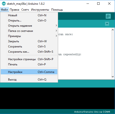
- In the Arduino IDE application interface, a team is selected that is responsible for creating a library called OneWire library. This action is performed by selecting the Add Library line in the interactive menu of the Sketch application. In the Russian-language version of the software, this item is designated as "add a library".
- After creation, you can go to the library and find in it a file for programming the instrument controller called D158x20. This line is located in the "Examples" subdirectory of the main drop-down menu "File".
- In the new window that opens, select the OneWire directory, which will contain the desired file D518x20_Temperature.
- The last step is to adjust the factory settings from 10 pin to 2 pin for stable operation of the equipment and obtaining reliable data in real time.
When the work is completed, a text with the input parameters will appear on the indicator of the device with the software, among which there will be a unique serial number of the sensor, as well as an indicator of the current temperature in the cold room where it is mounted.
Technical capabilities of the OneWire library
The OneWire library is an integral part of the software. The range of tasks that can be solved using this add-in includes the following features:
- Search and identification of each sensor connected to the system with automatic fixation of its unique code. To perform a search, enter the search (addressArray) command in the dialog box. If any device is not registered in the system, the user will see a false error message.
- OneWire can also search the primary device after issuing the reset_search command.
- If all settings have been reset, the library independently selects the device, writing a cyclic 56-bit ROM code to it. To perform this operation, the user specifies the select (addressArray) command.
- The write (byte) command provides writing bytes of information to the device when it is powered from the external network.
- The write (byte, 1) command performs the same function, but with a parasitic way of powering the controller.
- If necessary, the library allows the operator to read the incoming and stored information received for processing from temperature sensors. This process is performed by the read command.
- Cyclic redundancy check CRC activation. Command - crc8 (dataArray, length), where dataArray means the ordinal number of the selected array for storing data, length - the length of the digital code.
- The library allows you to configure the power on the sketch, depending on its type and the corresponding line - 65 or 10.

This universal add-on can independently issue commands in the form of bits, namely:
- 0x44 - a code responsible for temperature measurement with subsequent transmission and fixation of incoming data.
- 0xBE - the process of step-by-step reading of the sensor readings is started.
- 0xB8 - data is copied into bytes.
- 0xB4 is a code that allows quick switching of the type of power supply from a parasitic source to an external source, and vice versa.

Correct configuration of the library and knowledge of all commands will allow the user to easily navigate the software interface, quickly receive incoming information and change the basic user settings. As a rule, each dispatcher has a printout with all digital codes for quick intervention in the system.
Permissible operating parameters of the DS18B20 temperature meter
Any device for measuring temperature has parameters at which it can be operated without the risk of breakdown and malfunction. For the device under consideration, the maximum permissible parameters are given below:
- The voltage at which the uninterrupted operation of the device is ensured is from 3 to 6 V. If the real indicator is lower, the user will not be able to read the readings, since noise will appear on the line, and if the limit values are exceeded, a short circuit may occur, followed by burnout of the contact.
- The range of measured temperatures is from -55 ℃ to +125 ℃. In this case, it makes no sense to talk about any extreme values, since the range specified by the manufacturer is suitable for operating the device in any conditions.
It should be noted that long-term operation of the DS18B20 at the extreme operating parameters can significantly reduce the life of the device, and it will fail in a short time.

Algorithm for connecting several temperature sensors to one communication channel
As mentioned above, several temperature sensors can be connected to one bus at once for the possibility of dispatching the state of the cargo in the refrigeration unit from one information reader. To do this, you need to include a resistor in the circuit, and then perform several operations:
- Each new device must be connected in parallel, that is, reading information and transmitting a digital signal to the communication channel occurs from each sensor in an independent mode.
- In the OneWire library, parameters are set to search for each of the sensors, followed by registration of unique codes.
- The resistance of the resistor depends on the number of devices included in the system, based on the average resistance parameters of 100 - 150 Ohm for each sensor. Thus, the optimal resistance of the resistor when 10 sensors are connected to the system at once will be 1.5 - 1.6 kOhm.
- The resistor connects directly to the Arduino controller board.
After connection, the user gets the opportunity to address each sensor, and an alarm signal when the limit threshold is exceeded will be sent in automatic mode.
Temperature sensor compatibility with GPS tracker
The DS18B20 sensor is widely used in cold logistics. When transporting perishable goods, the driver cannot always monitor the microclimate inside the refrigerator, especially if the goods are transported without the participation of the forwarder. In such cases, temperature data is transmitted to the dispatching console remotely using a GPS tracker.
The device for wireless data transmission records the actual temperature in the refrigerator, allowing the operator to read these indicators, and, in the event of an emergency, the alarm signal is automatically sent to the monitoring system. For the GPSM Pro GPS tracker to work together with the 1-Wire DS18B20 temperature sensor, the following conditions must be met:
- After installation inside the refrigeration unit, the sensor is connected using a standard cable to a GPS beacon installed outside the cold circuit.
- The software is being configured with the setting of the boundary parameters for triggering the alarm.
- The data is sent to the controller, recorded by the GPS system and transmitted to the dispatching console.
- For the convenience of reading information and a quick response to an alarm, the notification of temperature fluctuations can be sent not only to the installed software. Information can come to the screen of a mobile phone in the form of an SMS message, as well as arrive along with incoming correspondence to an e-mail box. This allows you to get information not only to the dispatcher, but also to the driver.
If a problem is detected, the dispatcher of the logistics company immediately informs the driver or freight forwarder about the problem. This makes it possible to prevent the measurement of the temperature regime in the refrigerator in time and save the load.
Briefly about the main
The DS18B20 temperature sensor can be purchased from our online store at the best price among the competition. We work directly with the manufacturer and have preferential terms for wholesale deliveries. Our company is also engaged in the implementation of the related interface and GPS systems. The ready-to-use system provides the ability to remotely dispatch the state of the cargo when performing cold logistics.
The product represents the best value for money. When developing this high-precision device, advanced technologies were used, which allow obtaining information about the condition of the cargo in real time with a minimum error in calculations. If it is necessary to install the sensor in a chemically aggressive environment, customers have access to improved instruments with a stainless steel probe, which have increased corrosion resistance.
| Specification | |
| Consumption current | 1 mА whith 12V |
| Length of cable | 1.5 m |
| Measurement range | -55°C..+125°C |
| Power supply voltage | 3.0V - 5.5 V |
| Interfaces | 1-Wire |
Tags: temperature, controller, sensor, meter, logistics, refrigerator, dispatching, vehicle, operator, data
- Brand: Bitrek
- Product Code: DS18B20
-
- Availability: In Stock
- Guarantee: 12 months


